ALL ABOUT LONG TERM BEHAVIOR

Why Hilti injection mortar systems are for the intended use for at least 50 years

Background

Fundamentally, all type of safety relevant anchors should be designed in such a way, that they are resistant and durable under service loads and provide an adequate margin of safety against failure. Therefore in the European Union, United States and other countries, approval processes exist to provide an independent assessment. Approvals are based on tests intended to verify the suitability of a system and to determine the admissible service conditions.


Suitability tests are designed to verify the proper function of the anchor under unfavorable application conditions. These tests are generally conducted in concrete with a strength lower and upper end of the usual field of application and may include tests in cracked and non-cracked concrete specimens depending on the intended use of the anchor. The effects of installation variances are checked in detail, if relevant. Design parameters which are product specific and therefore cannot be established theoretically are determined via admissible service conditions tests.


Bonded anchors with a standard anchor rod and bonding material can be evaluated e.g. according to ETAG 001, part 5 (while taking account of the general part (ETAG 001, part 1) is mandatory), and AC 308, Acceptance criteria for post-installed adhesive anchor elements. AC 58 will not be taken account of in the given abstract. ETAG 001, part 1 (part 5)  is written on the assumption that the estimated working life (period of time which the performance of the product are maintained – under corresponding service conditions – at a level compatible with the intended use conditions) of the anchor for the intended use is at least 50 years. Note that AC 308 is base substantially on Part 5, Bonded anchors of the European Technical Approval guideline (ETAG 001)


In general, the following tests are the most relevant concerning the long term behavior of adhesive anchors:

  • Functioning under sustained loading (Creep test)
  • Crack movement test
  • Functioning under freeze/thaw conditions
  • Tests for checking durability

Functioning under sustained loading (creep testing) or why everything flows

Fig. 1 Everything flows exemplarily shown on fold mountains

Creep is a low and continuous de-formation of a material under sustained stress 
and is mainly influenced by the following parameters (see Fig. 1):


(a) Material/product

(b) Load level and duration

(c) Temperature

(d) Installation quality.

The creep behavior (deformation under sustained stress) of Hilti HIT-RE 500, Hilti HIT-HY 200 or upcoming future products is not equal or comparable and cannot be foreseen. Therefore this behavior is tested and assessed during the approval procedure.


It is assumed that bonded/adhesive anchors, reaching a limiting displacement value during the working life will fail by means of pullout failure.


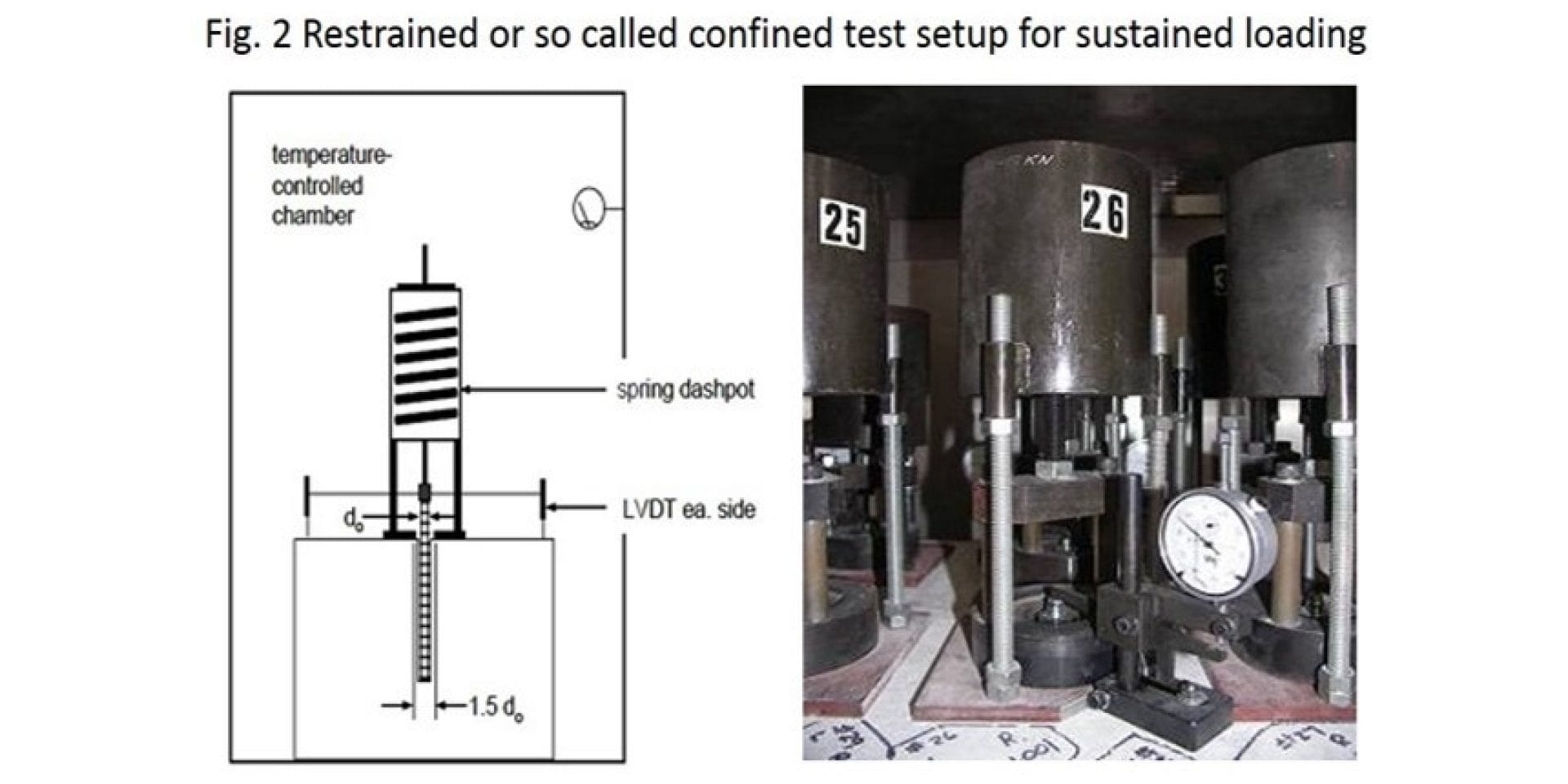
It is obvious that the creep behavior for bonded anchor system should be tested for failure mode “bond/pullout” failure (failure between the interface mortar/concrete) due to the fact that in this case the behavior is linked with the used injection mortar. Therefore the test should be performed as restrained or so called confined tests as shown in Fig.2. In a confined test setup the bonded/adhesive anchor will be loaded by means of a spring through a baseplate with hole clearance. The steel plate on top of the concrete surface prevents concrete cone failure mode, consequently only steel or pullout failure are possible. Steel failure should be avoided by choosing the correct embedment depth.


It should be noted that the following explanation is simplified without taking account of the different requirements stated in the relevant guidelines.


However in all approvals the fundamental premise used for evaluating the long term performance of adhesive anchors is namely, that relatively short term tests results may be extrapolated to the predict long term behavior.

It is clear; nobody wants to wait 50 years for an approval!

Please enter alternative text here (optional)

The general approach of testing for the response on sustained load consist of subjecting a bonded anchor (medium size M12) installed in a concrete block to an appropriate embedment depth of the mean ultimate tension strength measured in tests at room temperature. The load is maintained over a period of at least 42 days (1008 hours (ETAG 001 and ACI 308)) with the displacement measured in given intervals (see Fig. 2).


These tests have to be conducted at two concrete temperatures: standard temperature (room temperature) and the maximum long term elevated concrete temperature – temperature is an influencing factor - established for the bonded/adhesive anchor system. The resulting displacement measurements are then extrapolated by using an extrapolation equation commonly named as the Findley Power law or Findley creep law to 50 years (standard temperature) and 10 years (maximum long term elevated temperature).


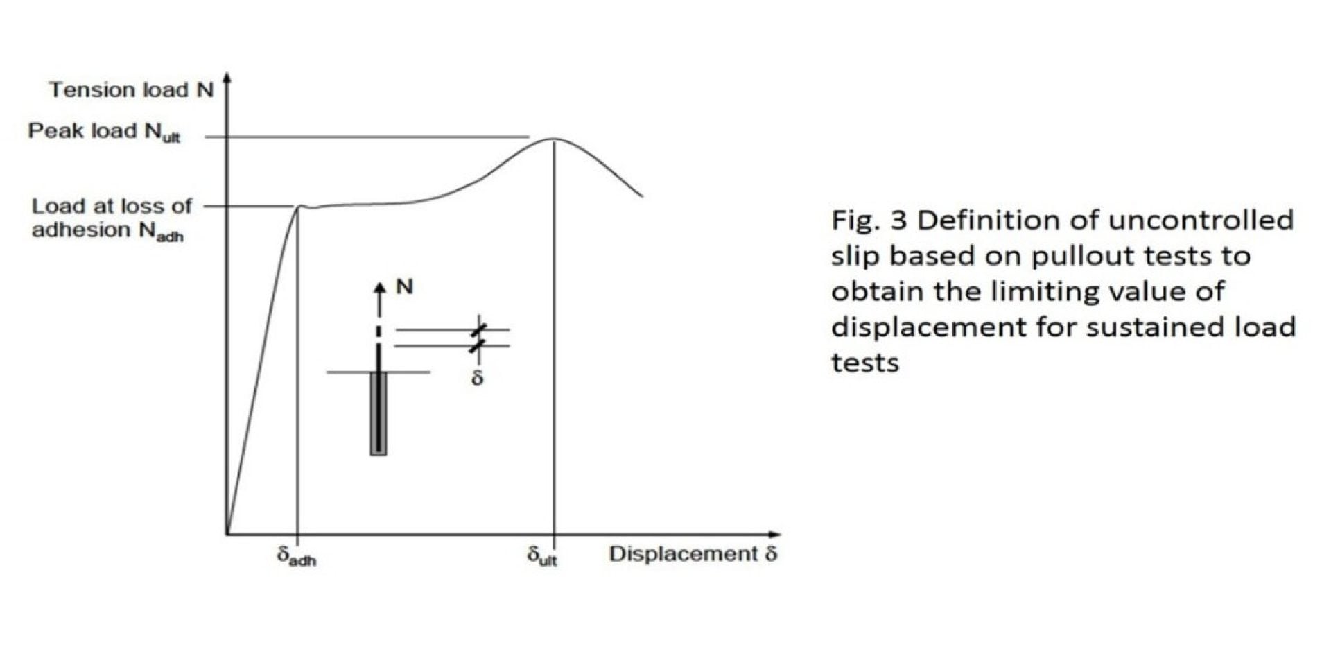
The extrapolated displacement of the sustained load test is compared to the mean displacement associated with “loss of adhesion” in confined “normal” tension test conducted at the respective temperatures. The limiting and acceptable displacement “loss of adhesion” may be explained as follows (see Fig 3). With bonded anchors uncontrolled slip occurs when the mortar with the embedded part is pulled out of the drilled hole, because then the load displacement behavior depends significantly on irregularities of the drilled hole.


The corresponding load (bond stress) when uncontrolled slip starts is called “load at loss of adhesion” Nadh (tadh). Nadh (tadh) is evaluated for every test during the approval procedure


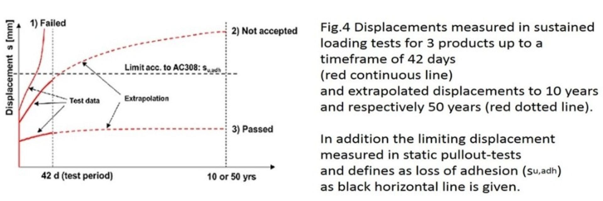
Fig. 4 shows exemplarily the possible results of tested sustained loading behavior of 3 possible products. In Fig. 4 the displacements measured in sustained tests as a function of time (up to 42 days) are shown (continuous red line) while in addition the extrapolated values with help of the Findley equation is given (red dotted line) for the three products. To assess these extrapolated values the horizontal dotted line represents the limiting maximum acceptable displacement, known and as explained as “loss of adhesion” where uncontrolled slips start.


Please enter alternative text here (optional)

1)  Failed 

Product 1 applied with a specific sustained loading failed already during the 42 days creep test (see continuous red line “1 Failed” in Fig. 4), by means of pullout failure indicated by an over-proportional increase of displacement. Obviously this bonded anchor system is not suitable for the applied load and temperature range. In that case the possibility of reducing the load may be checked while this reduction of the sustained load results in overall reduction of the basic characteristic bond strength values for the complete product as given in the approval.

Fig.4 shows additional two red continuous curves where the bonded anchor system did not fail by means of pull-out failure during the first 42 days. However, only one product is suitable.


2) Not accepted 
 

In case of the red line “2) not accepted “the measured displacement within the 42 days increased but the bonded anchor was not pulled out. However the  extrapolated displacement values (dotted red line) as described above shows significant lager values compared to the limiting displacement in case of” loss of adhesion” (black horizontal dotted line). Based on ETAG 001, part 5 and ACI 308 it is assumed that anchors, reaching this limiting displacement value of “loss of adhesion” during sustained loading will fail by means of pullout failure. This interpretation for the creep behavior is well established. However, tests indicate, that this behavior may be mortar type dependent.Based on the requirements stated in the approval this anchor system is also not suitable for sustained loading under the tested conditions.

The sentence is so important that it is worth to read again.


It is assumed that anchors, reaching this limiting displacement value of “loss of adhesion” during sustained loading will fail by means of pullout failure. This interpretation for the creep behavior is well established.


This sentence should be taken into account if prove loading is performed in combination with an assessment on site in case of an overhead application under sustained tension load. Even if prove loading was done and the results indicated that the required load can be applied on the anchor, no conclusions can be drawn concerning the sustained load behavior if only load values are considered.


3) Passed 


The continuous red line “3) Passed” shows the measured and the extrapolated values (red dotted line) of an anchor system which fulfills the requirements concerning the displacement. This is reasonable due to the fact that extrapolated displacement is smaller compared to the measured displacement in case of loss of adhesion. Therefore injection mortars showing this behavior are verified for sustained loading under the tested boundary conditions. This behavior is covered in the basic characteristic bond strength values provided in the relevant approval document.


It should be noted that the verification is only valid in case of a proper installation of the system as given in the IFU. Evidence indicates that presence of entrained air bubbles and voids caused by adhesive run are particularly relevant to long term behavior and can aggravate the creep response of anchors subjected to sustained tension. Therefore measures are taken during product development by Hilti to prevent adhesive loss and air entrainment. This includes Hilti injection equipment such as piston plugs fitted to the end of the injection tube.

Environmental factors (freeze/thaw conditions and aggressive, reactive substances

Please enter alternative text here (optional)

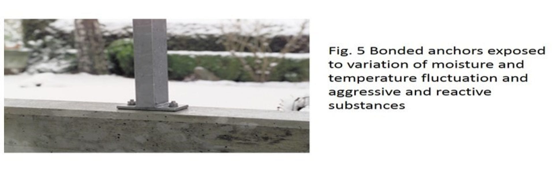
The discussion before regarding sustained loads applies to bonded anchors in dry interiors at a constant temperature. Bonded anchors in exterior application can be exposed to variation in moistures content of concrete, as well as temperature fluctuations and freeze thaw cycles (freeze-thaw conditions).  Furthermore they may be subjected to aggressive/reactive substances.


Based on test performed on site in earlier years (~1985) it was shown that the displacement of sustained loaded anchors increase or non-increase based on the used resin under freeze thaw cycles. Therefore this behavior has to be checked in tests.


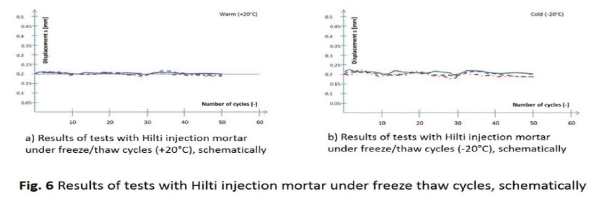
These tests are performed in non-cracked, freeze thaw resistance concrete while the test setup is comparable with the one shown in Fig. 2. However, the top of the test specimen with the installed bonded anchor is tapped with water and afterwards sustained loaded. The value of the applied sustained load is based on the characteristic bond resistance in case of pullout failure for non-cracked concrete C50/60. The sustained loaded anchors are attacked with 50 freeze thaw cycles between -20°C to +20°C (50 years). During these tests the measured displacement should be constant during the whole test procedure.  Measured displacement as a number of the applied freeze-thaw cycles are exemplarily shown in Fig. 6 for e.g. Hilti HIT-RE 500 or Hilti-HY 200 in a linear scale. The increase of the displacement is almost zero during the 50 freeze/thaw cycles. Therefore the displacement behavior fulfills the requirement according e.g. ETAG 001 and AC 308.


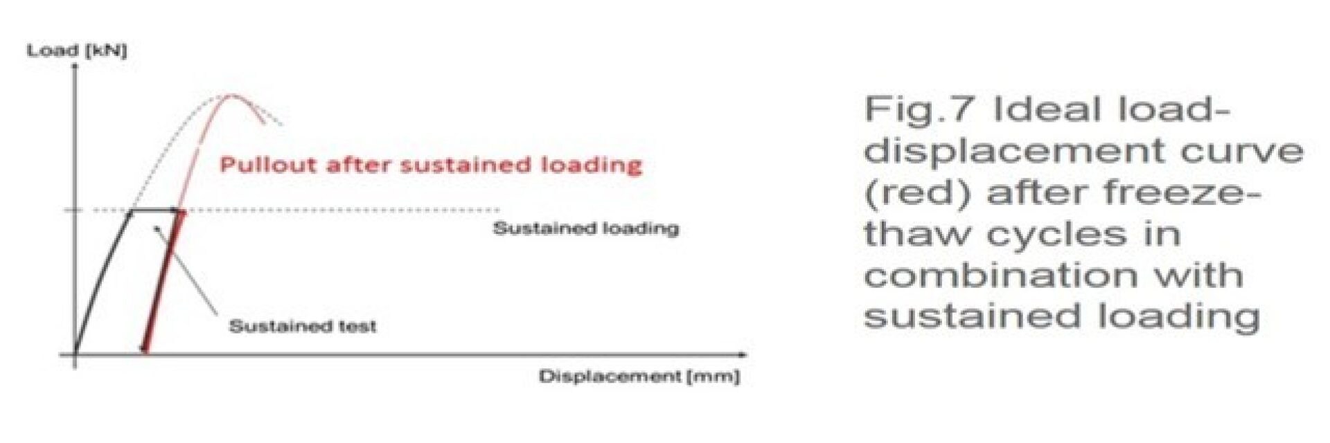
After the freeze thaw cycles the bonded anchor is unloaded and confined pull-out tests up to failure are performed while at least 90% of the pullout load compared to the pullout load of the standard reference test should be reached. Fig. 7 shows the ideal behavior of the load displacement curve after freeze-thaw cycles.

Please enter alternative text here (optional)

Therefore injection mortar showing this behavior are verified for the influence of freeze/thaw cycles during lifetime This behavior is covered in the basic characteristic bond strength values provided in the relevant approval document.


Please enter alternative text here (optional)

As explained above bonded anchors may be subjected to aggressive, reactive substances. Experience in the past showed that injection mortar systems under chemical attack show a significant reduction of load values compared to the load values under “normal” conditions. This is based on undesired chemical reaction.

Please enter alternative text here (optional)

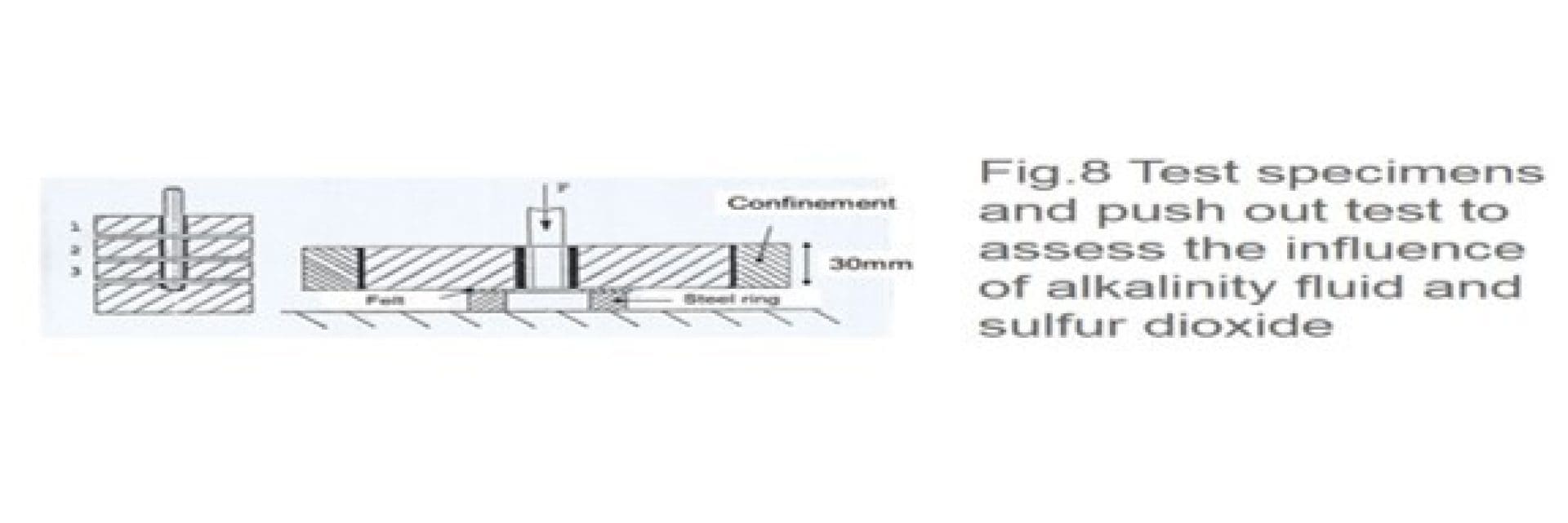
To check the influence of environmental conditions slice tests will be performed according to ETAG 001and AC 308. The concrete slices with Hilti injection systems are produced from concrete cylinders cut into slices (see Fig. 8). Then, slices are stored 2000 hours under normal climate condition (reference test), for 2000h in a fluid with high alkalinity (pH13.2) and 80 cycles under sulfur dioxide. From the failure loads measured in push out tests (not pullout test) conducted after the storage (see Fig. 8).


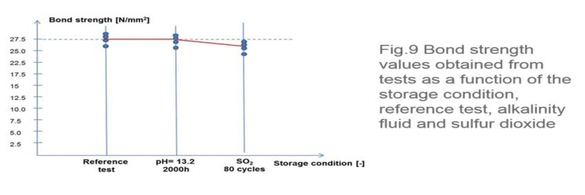
Afterwards the load/bond strength values are compared with the reference test (normal condition) while a bond strength (load) reduction of 10% is acceptable for sulfur atmosphere. No reduction of load values is acceptable in case of alkalinity fluid.  The schematically calculated bond strength values are plotted in Fig. 9 as a function of the storage conditions. It can be seen that the bond strength values evaluated from the reference test and the tests in alkalinity fluid are nearly identical. The reduction of bond strength under sulfur dioxide is less than 10%. Therefore the requirements concerning durability are fulfilled. 

Please enter alternative text here (optional)

Therefore injection mortars showing this behavior are verified to resist chemical attack during life time. This behavior is covered in the basic characteristic bond strength values provided in the relevant approval document.

Crack movement test or why cracks open and “close” in reality

As mentioned before “crack movement tests” can also be taken into account when talking about the long term behavior of adhesive/bonded anchors.  In the design of reinforced concrete flexural or tension components, a cracked tension zone is assumed because concrete possesses relatively low tensile strength, which may be fully or partly used by internal or restraint tensile stresses not taken into account in the design. Experiences have shown that crack widths resulting from primarily quasi permanent loads (dead load plus fraction of live load) do not exceed the value of w95% ~ 0.3mm to 0.4mm. Therefore test in cracked concrete should be performed if cracked concrete is intended for use.


Besides static pullout test in cracked concrete during the approval procedure tests in opening and closing cracks are performed. Without getting in detail of the test procedure, the tests are conducted as follows:


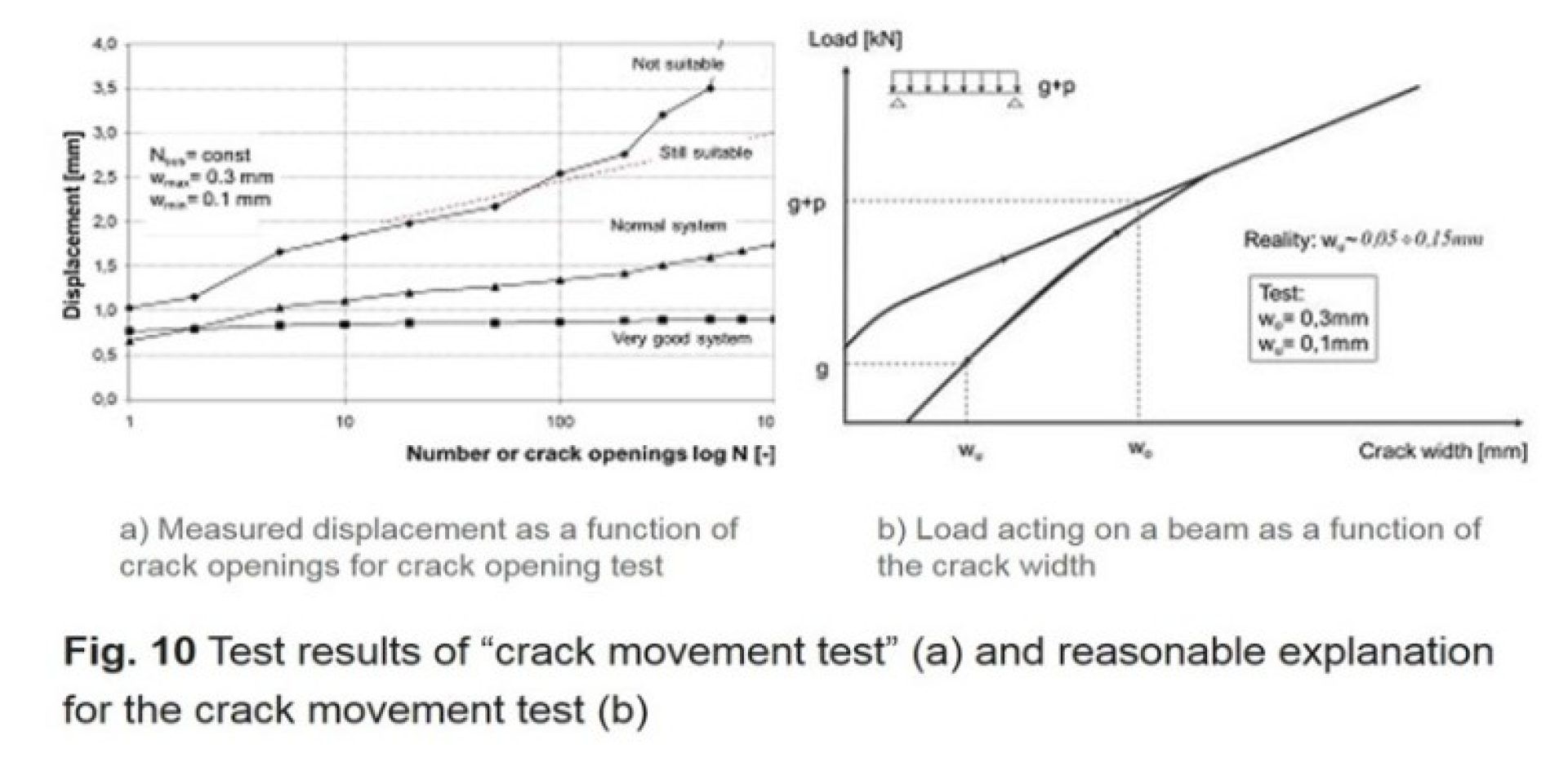
After installing the bonded/adhesive anchors in cracked concrete the anchors are sustained loaded based on the characteristic load evaluated in short term test. While the anchors are loaded under tension, cracks are open between 0.1mm and 0.3mm 1000 times and the displacement of the anchor under tension is measured. During these tests the measured displacement should be below the constant value of 3mm.


The value of 3mm is historically based on the allowable displacement of pipework where the support can be still assessed as “rigid”. In case of larger displacement the support has to be calculated as elastic.


Fig. 10a shows the results of 3 different products by means of plotting the measured displacement as a function of the numbers of crack openings.  While two systems would fulfill the requirements concerning the maximum displacement the other would not fulfill the requirements due to the fact that measured displacement is larger than the limiting displacement of 3mm. The next question would be: “Why do we do that?”,

Please enter alternative text here (optional)

As a structure responds to permanent load it experiences displacement and consequently deformation. This deformation leads to the formation of cracks. This behavior is schematically given in Fig. 10b. In Fig. 10b the permanent load “g” and variable load “p” are given as a function of the crack width for a beam. In the life of the beam probably no cracks will occur if the permanent load is acting on the beam the first time.


However if the variable load will be taken into account in combination with the permanent load (g+p) the deformation will increase and leads to opening of cracks in the beam. As mentioned above the crack width will be around 0.3mm. If the beam will be unloaded to a level of the permanent load again the deformation will decrease be means of reducing the crack width. However due to the rough surface of the crack surface the crack will not be closed to zero. Therefore the lower crack width is around 0.1mm. During the life of the beam this crack opening will be repeated while ETAG assess 1000 openings and closing for representing the life-time of the adhesive/bonded anchor.

Summary

The estimated working life of Hilti injection mortar tested according to EATG 001ETAG 001, part 5 and ACI 308 is at least 50 years. This is based on the fact that the decisive influencing parameters on the long term behavior of bonded/adhesive anchors are covered by the following tests:

  •  Functioning under sustained loading (Creep test)
  • Crack movement test
  • Functioning under freeze/thaw conditions
  • Tests for checking durability


The behavior of the bonded/adhesive anchors in the above mentioned test is taken account of in the basic characteristic bond strength values provided in the relevant approval document.


Hilti injection mortar = Approved long term behavior


Ask our engineers